 ??? ## Welcome and Introductions Timing: 10 minutes \(plus 10 minutes for class to introduce themselves.\) --- # Course Summary This course will give technicians a basic understanding of the tools needed to succeed in their field operations role and will guide them through the integration of one configuration type as a case study. The course will also familiarize technicians with and instruct them to apply the site configuration design documents and MOP Documents such that the technician can successfully integrate all company approved site configurations. ??? ## Instructor Notes **Say**: * This presentation is a step by step process that provides you all of the information that you will need to integrate and replace a DUL/S into the network. * There are several links included in this document that you will need to reference based on the current site configuration as well as diagrams on the proper connectivity points as you proceed in the installation process. --- # Course Chapters * Course Pre-Test * Tools of a Technician * Get to Know Your Site * Know How to Connect to Your Site * Prep Work * At the Site * Install Your Hardware * Post Hardware Installation * After Switch Ops Reviews the Site * Common Post Integration Alarms * Call Testing * Replacing DUS/DUL * Post Course Test --- # Pre-Course Test - What You Will Learn After completing the pre-course test, you should be able to: * Identify course topics you will need to acquire more knowledge about. --- # Pre-Test Questions: Questions 1-3 Which technologies are in mixed mode in the 704G configuration? 1. L2100 and L1900. 2. U2100 and L2100. 3. L1900 and GSM. 4. L1900 and U1900. 5. None of the above. Which technologies are supported in the 707A configuration? 1. L700 and L1900. 2. U2100 and GSM. 3. L700 and U2100. 4. L1900 and U1900 and L700. 5. Both 1 and 2. What is the DU type required for L2100 in the 702Cu configuration? 1. DUL20. 2. DUG. 3. US31 or DUS41. 4. DUW30. 5. None of the above. --- # Pre-Test Questions 4-6 What is the radio building block of LTE in a 702D configuration? 1. RBB12_1B for L2100 / RBB24_1A for L700. 2. RBB44_1D for L2100 / RBB22_1B for L700. 3. RBB11_1A for L2100 / RBB22_2B for L700. 4. RBB22_2B for L2100 / RBB11_1A for L700. 5. None of the Above What is other name for XMU03? 1. XMU Multiplexer 2. Baseband R503 3. DUL Multiplexer 4. XCU Multiplexer 5. None of the above 6. You don’t have VPN connection on site, what is the method to download existing CV from the DUL/DUS locally? --- # Pre-Test Questions: Questions 7-9 On the process of commissioning a DUL/DUS, the file transfer for the software basic package is completed and the reload command is executed, what is the next step? 1. Set the IP address. 2. Format the DUL/DUS. 3. Set the clock. 4. Begin transferring the upgrade package. 5. None of the above. If you don’t set the time correctly on the DUL/DUS, what is more likely to happen? 1. Your DUL/DUS will shut down. 2. You will not be able to load the O&M script. 3. It puts the license in the outdated state and a license mismatch alarm’ is more likely to come up. 4. You will not have connectivity to site. 5. None of the above. Why is it necessary to ‘soft-lock’ the sector/sectors before doing maintenance work such as replacing a DU, RUS, RRUS, AIR or any hardware that will disrupt traffic? 1. To ensure NOC and RAN departments will be aware of your work. 2. To ensure proper hand-over of traffic to neighboring cells. 3. To prevent dropped calls which could negatively impact the site’s performance and the company as a whole. 4. To prevent disruption of any ongoing 911 emergency call/s. 5. 1, 2 and 3. 6. 2, 3, and 4. --- # Pre-Test Questions: Questions 10-12 When a ctor is in the ‘shutting down’ status after initiating a soft-lock, what is happening at this moment in time? 1. The sector is waiting for any available UEs to make another call. 2. The sector is being forced to shut down just like when you initiate a ‘lock’ action command. 3. The TX power of the radio/s in that sector is being gradually decreased in such a way that the ongoing calls will be handed over to the next available sector/cell to prevent drop calls. 4. The sector is being forced to be in a degraded state so that proper handover will be initiated. 5. None of the above When connecting your laptop to a DUL/S what port does the Ethernet cable get connected to? 1. LMT A 2. TNA 3. LMT B 4. ET A 5. None of the above When connecting to a DUL/S what is the default ip address of the node? 1. 169.254. 2. 169.254.1.15 3. 192.168.0.1 4. 169.254.1.10 5. None of the above --- # Pre-Test Questions: Questions 13-15 Where is the location for the latest LTE upgrade and basic packages? 1. ANPS. 2. ENPS. 3. InfoRouter. 4. Ericsson IM. 5. None of the above. What command brings the node into backup state? 1. reload. 2. ifconfig. 3. reload--. 4. readclock. 5. Both 1 and 4. What are the steps to format your DUL/S? 1. Bring the du into back up state(reload --), format the node and set the node ip. 2. Format, set the node ip, and set the password 3. Set the password, reload the node, format the node. 4. Set the node ip, format the node, reload the node. 5. None of the above. --- # Pre-Test Questions: Questions 16-18 What location would you transfer the Upgrade package if you want to create a combination package for integration? 1. The /c2/tmp folder of the basic package. 2. the /d/configuration folder of the node. 3. the /c/license folder of the node. 4. the /c/users folder of your laptop. 5. None of the above. Where do you connect the Ericsson supplied serial to RJ-45 cable when connecting to a DUL/S? 1. TN B. 2. EC. 3. LMT A. 5. LMT B. 6. None of the above. What tool is used to load the OAM script to the DUL/DUS? 1. Element Manager. 2. Putty. 3. LTE Provisioning Tool. 4. OMT. 5. Both 2 and 4. What tool is used to load the OAM script to the DUL/DUS? 1. Element Manager. 2. Putty. 3. LTE provisioning Tool 4. OMT. 5. Both 2 and 4. --- # Pre-Test Questions: Questions 19-21 What port on the DUL is used for element manager? 1. TN A. 2. EC. 3. LMT A. 4. LMT B. 5, None of the above. If asked to integrate a new site, what document shows you the sites proposed configuration? 1. EME study.pdf. 2. RFDS.pdf. 3. Oamaccess.MO. 3. Both 1 and 3. 4. None of the above. What does the design specification document contain? 1. node IP address. 2. address to site. 3. specific design information for each type of supported configuration. 4. troubleshooting guide. 5. None of the above. --- # Pre-Test Questions: 22-24 After loading the O&M script on your DUL/S what step should be taken next? 1. Create a CV. 2. Reload the site. 3. Format the node. 4. Load site specific scripts 5. None of the above. Once your finish loading your OAM script you should? 1. Ping the site from SLIPED. 2. Contact the switch to complete the integration. 3. Connect port TN A to Port 7 on your router. 4. Both 1 and 3. 5. All of the above. There is no connectivity to port 7 on the CSR from your DUL/S after running your O&M script the next steps are to? 1. Verify your cabling from DU to port 7. 2. Verify the CSR port is active. 1. Both 1 and 2. 3. Check cabling between DU and RU. 4. None of the above. --- # Pre-Test Questions: Questions 25-27 For a site configuration having a radio building block of RBB12_1A, the no. of TX branches and the no. of CPRI cable for a radio is? 1. 1 &1. 2. 2 &1. 3. 1&2. 4. 4&1. 5. None of the above. In a site with XMU, what port/s were not being assigned in all T-Mobile configuration? 1. 1,2,9,10,11,12,13,14,15. 2. 1,3,16. 3. 3,4,5. 3. 3,4,5,6,7,8. 4. None of the above. On Design Specification 704E, what technologies are going to in-service? 1. L700, L19,L21,U21. 2. U21,U19,L900. 3. GSM,L21,L700. 4. L700,GSM. 5. Both 1 and 3. --- # Pre Test Questions 28-30 hen integrating a 703Bc configuration what Radio building block is recommended for L2100? 1. RBB22_1B. 2. RBB22_2C. 3. RBB11_1A. 4. RBB24_1A. 5. None of the above. In a 707C hardware configuration, there are 3 radios per sector and they are? 1. Two RRUS11 B2, )ne RRUS11 B12. 2. Two RRUS11 B12, One RRUS11 B4. 3. One RRUS11 B2, One RRUS11 B4 and One RRUS11 B12. 4. One RRUS11 B12, One RRUS01 5. One RRUS11 B4. 6. None of the above. What function does the LTE provisioning tool provide? 1. Loads the basic package. 2. Loads the license key. 3. Formats the DUS hard drive. 4. Loads the OAM script. 5. None of the above. --- # Pre Course Test - Summary At the end of this chapter, you should be able to: * Identify course topics you will need to acquire more knowledge about. --- # Download the LTE Provisioning Tool What is the LTE ProvisioningTool? The LTE provisioning tool is used to load the OAM scripts to the Node.  1. Download the LTE provision tool from the ENPS website: http://enps.eng.t-mobile.com/(S(avivsfn13e0htcdw0ixzrep))/FileStore.aspx. 2. From the ENPS home page, select the DUL provisioning tool tap. 3. The tab will direct you to the downloadable file.  4. The provisioning tool is used to load the OAM scripts to the node.23.  5. When the tool was successfully downloaded, you will see the main view when opened.  --- # Tools of a Technician - What You Will Learn At the end of this chapter you will be able to: * Download the Provisioning Tool. * Familiarize yourself with the RFDS Data Document. * Download the Element Manager. * Identify Ethernet cables and when to use them. * Identify the items on the Vehicle Inventory Checklist. ??? ## Instructor Notes ### Classroom Detail Class Interactions Pause for questions at the end of each slide and encourage class discussion throughout. ### Class Activities Download software and review checklists. ### Knowledge Checks n/a ### Tools of the Technician - Materials and Equipment * Provisioning Tool. * RFDS Data Document. * Element Manager. * hernet cables. * Vehicle Inventory Checklist. **Say:** * Please ensure that you have the proper laptop and understand how to gain connectivity to the T-Mobile network which will allow you access to the various data points necessary to complete this training: http://enps.eng.t-mobile.com/(S(avivsfn13e0htcdvw0ixzrep))/FileStore.asp --- # Familiarize Yourself With The RFDS Data Document * In preparation for site integration, you should obtain a RFDS copy via the link RFDS.eng.t-mobile.com. Open and review the document. Familiarize yourself with this document’s structure.  ??? ## Instructor Notes **Say:** * The RFDS is the site data sheet that is designed by RF engineering. * It explains the site specific design plan. In the RFDS, you will find the site’s configuration details. * Most importantly, the proposed new design configuration and the existing configuration will be in this document. Please ensure that you obtain a copy of the RFDS document and familiarize the information and how it correlates to the particular site in your network: RFDS.eng.t-mobile.com. --- # Design Specification Document * Every type of configuration has a design specification document that describes in detail the supported hardware layout, radio configuration, carrier names and connectivity diagrams. * After first using the RFDS to find the new proposed configuration, you can search the RAN engineering share drive for the for the design specification for your particular configuration: * Ericsson Cell Site Designs: http://tm/SiteDesigns. * Use the link below to find the most current RAN supported design specification documents. * Take note of the proposed new configuration located in the top left of the document in the RAN Template box.  ??? ## Instructor Notes **Say:** If you are not completely sure of the site design you are preparing to work on, obtain a copy thru the above link in this slide and review in its ! http://tm/SiteDesigns --- # Tools Of A Technician * You can now select the folder that pertains to your configuration or enter your configuration into the search bar.  --- # Download The Element Manager * What is the Element Manager? Element Manager is the Ericsson user interface used for communication to the DU. 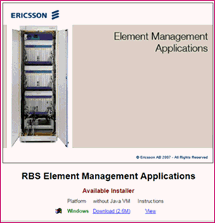 1. To download EM, you will need to be connected to a loaded DUL/DUS (see DU connection section). Once connected to the DU, use this link: http://169.254.1.10/em/index.html. 2. in your web browser to get to the software download page. 2. Follow the dl procedure. ??? ## Instructor Notes **Say:** * As a requirement you will need to utilize Java Rev 1.5 for downloading Element Manger to your laptop. * Once again, verify your network connectivity before you try to download a copy of Element Manager to your computer: http://169.254.1.10/em/index.html. --- # Save Design To A PC * Now that you have a copy of the design, save it to your PC. Review the document to have an understanding of what you can expect to see on site. ??? ## Instructor Notes **Say:** Please obtain a copy of Design sheet and familiarize yourself with the document as it relates to the site that you are going to integrate. --- # Identify Ethernet Cables and When To Use Them ## Materials and Equipment - Ethernet Cables You will need the following cables to communicate with the DUL/DUS from your PC: * Ethernet cable 6’ – 10’. * Ericsson provided serial cable * LMT splitter. * The Ethernet cable will go from your PC LAN to the LMT B on the DU. The local area connection will give you an IP connection to your DU. ??? ## Instructor Notes **Say:** Please ensure that you test any and all cables prior to going to the site. --- # Ericcson Provided Serial Cables * Ericsson provided serial cable. (Part # RPM919732/0500). * The serial connection goes from your PC com port to LMT A on DU. * Common uses – Putty, Tera Term. * Please ensure that you test any and all cables prior to going to the site. 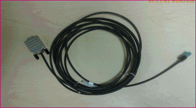 --- # LMT Splitter for DUS Only * The LMT splitter combines both Ethernet and serial in to one DU connection port (LMT). Ericsson provided serial cable. 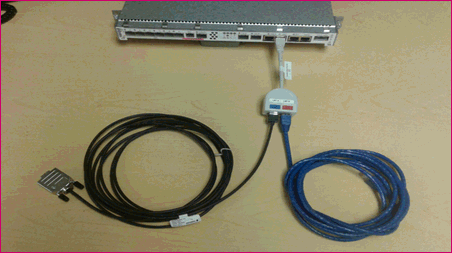 ??? ## Instructor Notes * Once again, please ensure that you verify the cables are the proper part number and test any and all cables prior to going to the site. --- # Identify the Items on the Vehicle Inventory Checklist. ## Materials and Equipment * Vehicle Inventory Checklist --- # Tools of Technician - Summary ## Vehicle Inventory Check List: * PC with DU connection cables – also a good idea to have a spare cable kit. * Spare DU. * Spare SFPs optical and electrical. Note - SFP’S need to match top/bottom (702C = RDH10247/2) * Spare CPRI cables. * Pre tested Ethernet cable for DU to CSR. * Spare GPS kit. * Spare DC power connection cables. * Having a heater and tarp with straps and bungies are also recommended for outdoor equipment.  --- # Get to Know Your Site - What You Will Learn In this chapter you will be able to: * Verify and if necessary, troubleshoot port connectivity. * Verify site connection. * Verify that prep work has been completed. * Identify the steps that you will perform at the site before you begin. * Identify common integration issues. ??? ## Instructor Notes ### What You Will Need for the Classroom **Timing**: 15 minutes, plus 5 minutes to complete the Ready to Move Forward questions on last slide) ### Materials/Equipment * Design Data Document ### What’s in this Section? * Design Data Document ### Class Interactions Pause for questions at the end of each slide and encourage class discussion throughout. ### Class Activities Review Design Data Document with class ### Knowledge Checks n/a --- # Understanding the RFDS Document There are three states of the RFDS. FOPS will only use the final version. The final version can be pulled from the Element Tool via the documents folder or other market depositories.  ??? ## Instructor Notes Once again please ensure that you are able to gain access to the various data points across the T-Mobile network so you can utilize them as reference in future topics. --- # Equipment in the RFDS ## Element/documents/SiteID/RF_Config_Final 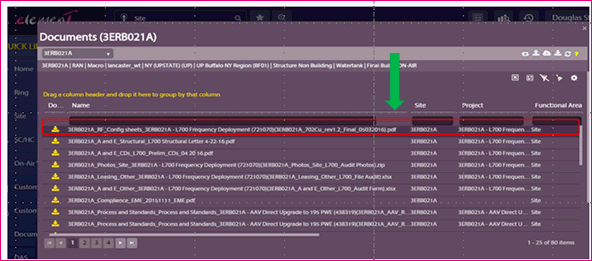 1. Now that you have pulled the new RFDS from Element, it can be used to help you understand which project the site falls under, the proposed configuration and the hardware to be deployed. 2. If the work to be done is an upgrade to an existing site, you will see the existing equipment and the proposed equipment in the RFDS. 3. Now that you have pulled the new RFDS from Element, it can be used to help you understand which project the site falls under, the proposed configuration and the hardware to be deployed. 4. if the work to be done is an upgrade to an existing site, you will see the existing equipment and the proposed equipment --- # Section 2 and Section 3 - Antenna Configurations * Section: 2 shows existing antenna configuration:  * Section: 3 shows proposed antenna:  ??? ## Instructor Notes **Say:** If you are not well versed on site configuration requirements are decided or how they are set up for a particular use, check with the RF Engineer that is responsible for the site that you are about to visit. --- # Section 5 – RAN Equipment  ??? ## Instructor Notes **Say:** Section 5 shows you existing/proposed - enclosure type, carrier baseband, digital units, Radios and SOW overview. --- # Section 6 – Antenna and Line Equipment   ??? ## Instructor Notes Section 6 describes the antenna and line equipment existing/proposed for each sector. --- # Information in the RFDS Now that you understating how to use the RFDS, you will be expected to find the following information: 1. Proposed new design configuration 2. What project you are working on 3. Existing equipment 4. Proposed new equipment 5. SOW overview 6. Proposed Baseband DU & radio equipment The information in the RFDS will give you a high level understanding of the configuration of your site. You are now prepared to review the design specification document for your specific configuration. --- # Format and Content of the Design Document ## RFDS INFO702CU Design Document from: http://tm/SiteDesigns:   ??? ## Instructor Notes **Say:** 1. Understand of format and content of the design document. 2. RFDS INFO 702CU Design document from: http://tm/SiteDesigns. --- # Table of Contents  ??? ## Instructor Notes The document has a table of contents that breaks the large document into sub categories. This simplifies the lengthy document into an easy to use information search guide. --- # Find\/Headings  ??? ## Instructor Notes By using the Find/headings, you can quickly jump to content that pertains to the work you are doing. --- # Know How to Connect to Your Site - What You Will Learn In this chapter you will be able to: 1. Connect to the T-Mobile Network. 2. Download the Element Manager. 3. Connect to your Site. ??? ## Instructor Notes ### What You Will Need for the Classroom ### Know How to Connect to Your Site Classroom Details ### Timing: 15 minutes ### What’s in this section? How to connect to your site. ### Class Ativities Students connect to their site. ### Knowledge Checks n/a ### Materials/Equipment Connection to T-Mobile site. Ethernet Cables. --- # Getting Started 1. Power on your DU(L/S). 2. Connect your Ethernet Cable to port LMT B and your Ericsson supplied Serial Cable to LMT A. 3. Open your network connections>Local area connections. 4. Click Properties and then select IP v4.  ??? ##Instructor Notes **Say:** Please ensure that you have a good working computer and have already verified connectivity to the T-Mobile network. --- # Properties  Select Properties and set your IP to connect to the default: * IP address: 169.254.1.15 * Subnet: 255.255.0.0 * Default Gateway: 169.254.1.10 --- # Download Element Manager Program Element Manager from the DUL/S: (http://169.254.1.10/em/index.html)  ??? ## Instructor Notes **Say:** If you still have problems gaining access to the network, reach out to the EIT Help Desk. --- # Run Element Manager Program  1. Click on Download and then Run. 2. Follow the steps to install the program. 3. Ensure you have Java version 1.5 on your local machine. If not, install it. 4. Open Element Manager (install instructions are contained in the Tech Tools sections). 5. Input the default IP Address for the DU(L/S) and click Connect in the lower right hand corner. --- # You’ve Got Connection! Below is what you should see upon successful connection to your site!  --- # Know How to Connect to Your Site - Summary You can now: 39. Connect to the T-Mobile Network. 40. Download the Element Manager. 41. Connect to your Site. --- # Prep Work - What You Will Learn In this chapter you will be able to: 1. Install and configure that necessary software configuration packages before arriving at a site. ??? ##Instructor Notes Once again, please be sure to review any and all documentation prior to going to the site to begin your work: enps.eng.t-mobile.com Ensure you know the site equipment configuration. This can be found in the RFDS, which should be provided upon notification of the upcoming integration. ###What You Will Need For The Classroom ###What’s in This Section? How to install and configure software prior to arrival on the site. ###Materials/Equipment * RFDS, Basic Package and Upgrade Package, FTP client, Elements Manager. * Ensure you know the site equipment configuration. This can be found in the RFDS, which should be provided upon notification of the upcoming integration. * Know what equipment will be on site(DUL or DUS). * Download the latest Basic Package and Upgrade Package for your configuration from the ENPS website here: ENPS .eng.t-mobile.com . ###Class Interactions * Class demonstration Pause for questions at the end of each slide and encourage class discussion throughout. ###Class Activities n/a ###Knowledge Checks n/a --- # Summary - Getting to Know Your Site You should now be able to navigate the Design Data document to find information about: 1. Cabinet type 2. Hardware kit needed 3. Carrier configuration 4. Connectivity diagrams 5. Radio configuration 6. Backhaul cabling 7. Digital and Radio building block ??? ## Instructor Notes **Review Objectives** **Discuss:** If you are still uncertain about aspects of the site, please reach out for support by either a peer and or your direct supervisor. Please ensure that the Technician knows how to find the correct Radio Building Blocks for their specific application. --- # RFDS Section 1 Review New site design configuration = What project = L700  ## Instructor Notes **Say:** Once again make yourself familiar with all site specifics and appropriate documentation. --- # Extract the Basic Upgrade Package 1. Extract the Basic and Upgrade packages (If needed). 2. Open the Basic package, navigate to the /c folder and right click to create a new folder called tmp. 3. Ensure you know the site equipment configuration, which can be found in the RFDS. The RFDS should have been provided to you upon notification of integration. ??? ## Instructor Notes **Say:** When extracting the upgrade package, ensue that the file is fully extracted(there are several folders). * Extract the Basic and Upgrade packages (If needed). * Open the Basic package, navigate to the /c folder and right click to create a new folder called tmp. * Make sure you know the site equipment configuration, which can be found in the RFDS. The RFDS should have been provided to you upon notification of integration. --- # Paste the Upgrade Folder For a DUS application, you are required to utilize the Ericsson provide splitter. 1. Copy and paste the entire upgrade folder into this folder. 2. Connect you laptop Ethernet port to the LMT B port on the DUL/S and the serial port to LMT A. 3. Set your laptop IP address to connect to the default node IP. (See connect to DU). --- # Open An FTP Client 1. Open your favorite FTP Client (WsFTP) and connect to the DUL/S default IP. 2. On the left hand side of the screen, navigate to your combined basic and upgrade package. 3. Open this file and the hard drive folder. 3. Select the c2 and d folders (CTRL-click on both). --- # Point to Remote Machine 1. Click on the arrow to point towards the remote machine and allow the files to transfer. --- # Open Another Terminal Emulator 1. When completed, you will need to open your terminal emulator and log in (if User/Pass word is required enter rbs / rbs). 2. Type in reload and hit enter to bring the basic package current on the DUL/S. 3. This will take a few minutes and once complete, log in server ready message on the screen. ??? ## Instructor Notes **Say:** 1. When completed, you will need to open your terminal emulator and log in (if User/Pass word is required enter rbs / rbs). 2. Type in reload and hit enter to bring the basic package current on the DUL/S. 3. This will take a few minutes and once complete, log in server ready message on the screen. 4. Set date and time using the ff command and format: setclock yyyy-mm-dd hh:mm:ss. 5. Once clock is set, type: reload to restart the DU to update the time/date. 6. When restart is completed, go to next step. --- # Open an RBS Element Manager 1. Open RBS Element Manager. 2. Type in the default IP into the connection block and click on connect. 3. Once the screen opens, upgrade your node. --- # RBS Element Manager - Navigate to Upgrade 1. Once the following screen opens, navigate to the upgrade and backup screen using the drop down menu. --- # Select New Upgrade 1. Right click the All Upgrade Packages screen.** 2. Select Create New Upgrade. 3. On the following screen, input the requested information. Your upgrade file location will be: /c/tmp/UPGRADE FOLDER/UpgradeFILE.xml ??? ## Instructor Notes **Say:** **Note:** Highlighted red should be replaced with the actual folder & file names --- # New Upgrade 1. Click on add in the lower right hand corner and wait approximately 30-45 seconds. 2. Close this window and click Refresh Tree in the lower the left hand corner. 3. Click on add in the lower right hand corner and wait approximately 30-45 seconds. 4. Close this window and click Refresh Tree in the lower the left hand corner. --- # Execute the Upgrade Package 350. Right-click the name of your Upgrade Package and select Install. A new window opens. 351. Click Execute in the lower right hand corner. ??? ## Instructor Notes **Note:** This takes roughly an hour for this new upgrade version. --- # Upgrade Package Name 1. Once complete, close this window and click Refresh Tree again. 2. Right click the Upgrade Package name again and select Upgrade. This process will complete in about 5 minutes. 3. Once you click on execute, there will be a series of windows that pop up. 4. Do not close these windows. 5. When progress bar reaches 16 out of 19, 'awaiting confirmation' will appear below the progress bar. --- # Close the Element Manager 1. You may close out all Element Manager instances now. 2. Reopen a new session using the default IP address. --- # Navigate to Upgrade and Backup 1. Navigate back to the Upgrade and Backup screen, using the drop-down menu. 2. Right - click the name of your upgrade and select Confirm Upgrade. This process will take approximately 30-60 seconds. 3. Once this is complete, close out the popup window. --- # Refresh The Upgrade and Backup Tree 1. Refresh the tree on the Upgrade and Backup window and verify the new upgrade is showing as Upgrade Completed on the right hand side of the screen. 2. Create a Post_Upgrade CV, following the instructions in the Load O&M document. 3. Refer to Load O&M document. --- # Open the DUL\/S Provisioning Tool 1. After loading the Basic and Upgrade Packages and prior to arriving on site, open your DUL/S Provisioning Tool. 2. This link is available at: http://enps.eng.t-mobile.com --- # Load the Market List 1. Load the Market List. 2. Select your market and then select your submarket. --- # Select List All Market Scripts 1. Click the List All Sub-Market Scripts and find your assigned site. 2. If your site is not shown on the list, call your local support and ask them to generate it. 3. When you find your site, click the box next to it and select Transfer Selected Scripts to Laptop. The script on the right side the screen appears. --- # Disconnect the VPN 1. Disconnect from VPN and Connect your laptop to port LMT B on the DUL/S using an Ethernet cable. 2. Click Select Site. 3. On the following screen, select Run. --- # Power Cycling the DUL\/S 1. Once complete, the site name will highlight green. If there are any errors along the way, try power cycling the DUL/S. --- # Create a CV or a DUL\/S 1. After the OAM script successfully runs, you will need to create a CV or the DUL/S will lose the OAM configuration. This can be done through Element Manager or via CLI. 1. From the Element Manager: * Click on the drop down menu and select Upgrade and Backup. * Click the CV tab on the right hand side of the screen. * In the lower right hand corner, click Create CV. --- # Enter the Required Information 1. Click on the drop down menu and select Upgrade and Backup. 2. Click the CV tab on the right hand side of the screen. 3. In the lower right hand corner, click Create CV. --- # Select the CV Name 1. Click Refresh in the lower right - hand corner of the screen. 2. Right-click your CV Name, and select Set Startable. --- # Show the List of Available CVS 1. Open your favorite terminal emulator and create a telnet or serial connection to your node. 2. Log in using the username and password for your site (LTE will always be rbs/rbs). 3. To create your cv, use the command cv mk (CVNAME - no spaces. You can use underscore if a space is required). 4. To set the CV startable, use the command cv set (CVNAME - The name must match exactly). 5. The command cv ls shows a list of all available cvs on the node and their status. 6. Power down the DUL/S and bring it out to the site with you. ??? ## Instructor Notes **Say:** **Note:** If you do not want to utilize Element manager you can utilize CLI. --- # Prep Work - Summary You can now: 1. Install and configure that necessary software configuration packages before arriving at a site. --- # At The Site - What You Will Learn In this chapter you will be able to: 1. Verify and if necessary, troubleshoot port connectivity. 2. Verify site connection. 3. Verify that prep work has been completed. 4. Identify the steps that you will perform at the site before you begin. 5. Identify common integration issues. ??? ##Instructor Notes ###What’s In This Section? * Port connectivity. * Site connection. * Prep work. * Steps that to at the site. * Common integration issues. ###Timing: 60 to 90 minutes ###Class Interactions Pause for questions at the end of each slide and encourage class discussion throughout. ###Class Activities n/a ###Knowledge Checks n/a ###Materials and Equipment n/a --- # Refer to the New RFDS 1. Upon arrival to the site, please refer to the new RFDS. See picture below: --- # Connect to Your DUL\/S 1. Connect your DUL/S to the router using a straight through Ethernet(CAT5E/6) cable to port 7 on the CSR(except SAR-A). 2. Verify connectivity by observing port activity and pinging the site : http://sliped.internal.t-mobile.com. 3. Login using your NT login information and input your selected site into the Search Cell --- # Look for DUL\/S eNode B 1 OAM 1. Look for DUL/S eNode B 1 OAM and click the Ping Radio button on the right hand side. It should come up successfully. --- # Troubleshoot Ping Attempt 1. If the ping does not come up as successful, verify your cabling and the port settings on your router via CLI. 2. You can either log in locally with a serial connection 115200 port speed, or remotely using the OAM IP for the CSR found in SLIPED, via an SSH connection. --- # Login with NT Login add graphic here. check instructor notes in deck --- # Select the Site 1. Click Select Site. 2. On the following screen, select Run. --- # Common Errors 1. Log in using your NT login information if the router is online. 2. Type in sh port 1/1/7 (if SAR M) or sh port 1/2/7 (if SAR F). The port should be Admin State Up and Oper State Up. 3. If admin is down, turn up the router port using the configure port 1/2/7 no shutdown command for a SAR F, port 1/1/7, if it is a SAR M. --- # Verify Site Configuration 1. Verify your site configuration using the RFDS provided by your manager or Site Development team. 2. Verify that the hardware is already present and on air. 3. Take the necessary precautions to prevent unnecessary outages (i.e. notify relevant parties of your site arrival (Switch, NOC, RF). 4. NEST the site and perform an inventory of your supplied hardware and parts. 5. Use the Site Design document for your specific configuration. 6. Design documents are located here: 7. Starting from Modernization up to AIR32 single band designs: http://tm/SiteDesigns 8. AIR32 dual Band and RRUS32 designs: http://tm/SiteDesignsNew --- # Verify Necessary Paperwork * Verify all necessary prep work has been completed by the tower crew and other vendors (i.e. RRUs installed in the appropriate location, power and fiber connected and routed neatly ( see the 3x6 diagrams on the right). --- # 3x6 HCS Connections add graphic here. check instructor notes in deck --- # Stuff to do Before Starting Site Work 1. Notify your management and switch/RF support via email or phone call that work will begin. 2. NEST the site using the assigned work order number. 3. Open the power upgrade MOP in the 702C folder located here and read through the necessary steps: https://docs.eng.t-mobile.com/Inforouter/docs/T-Mobile/Engineering%20and%20Operations/Procedures%20MOP%20SOP%20DR%20%20etc/MOP%20Library/RAN/Ericsson%20Network%20Modernization/Configuration%20702C/T-Mobile%20RBS6131%20702%20703%20Power%20Upgrade%20MoP.doc 4. Ensure you completely understand the work about to be performed before you begin: * Soft Lock the appropriate technology(ies), or ask the switch to do so for you if you do not have the appropriate access or knowledge. Wait until the site shows as locked in Common Explorer and an additional 5-10 minutes before proceeding. * Perform the necessary Steps in the 702-703 power upgrade MOP (section 3.4) paying special attention to step 3 Setting PDU 02 02 Dip Switches. Refer to the following diagram, also included in the MOP. ( See next slide for details). --- # Setting PDU 02 02 Dip Switches Add 3 images here. check deck for instructor notes --- # Post Integration Steps 1. Once your support team has completed their portion of the integration, continue to Post Integration Steps in this document. 3. Common integration issues: 4. O&M connectivity lost during the integration. 5. Hardware/Installation related issues: 6. Equipment not properly powering up. --- # Review Power Integration and Upgrade in MOPS !. Review power upgrade and integration MOPs in the 702C folder in the link below and read through it prior to performing any work: http://docs.eng.t-mobile.com/InfoRouter/docs/~F354720 2. Begin your work by following the steps outlined in Section 3.4 Site Specific Step by Step. 3. Remove the component no longer being used, as explained in the MOP/Design Document. 4. Install the new components provided in your kit including your preloaded DUL/S. 5. Connect all necessary cables to your DUL/S and verify connectivity to the site. This can be done by performing a ping through SLIPED. (sliped.internal.t-mobile.com) 6. If the ping comes back successful, reach out to your integration support and they can begin their process. 7. If the ping is not successful, refer to the Downloading the OAM Script document for troubleshooting steps. --- # At The Site - Summary You can now: 505. Verify and if necessary, troubleshoot port connectivity. 506. Verify site connection. 507. Verify that prep work has been completed. 508. Identify the steps that you will perform at the site before you begin. 509. Identify common integration issues. --- # Install Your Hardware - What You Will Learn After this chapter you will be able to: Identify resources you can use to solve discrepancies between the RFDS and the site. ??? ##Instructor Notes ###What’s in this section? Tool to troubleshoot site install discrepancies. ###Timing 10 minutes. ###Materials/Equipment n/a ###Class Interactions Pause for questions at the end of each slide and encourage class discussion throughout. ###Class Activities n/a ###Knowledge Checks n/a --- # Is the Site Up to Code? 510. Confirm that the site is built and cabled as per the RFDS/Design document. 511. Work with Market RF to resolve any discrepancies between RFDS and actual site build. ??? ## Instructor Notes Say: If you run into any issues, a good idea would be to reach out for support to a team member that has already completed this work so you can utilize them as a reference prior and during this maintenance procedure. http://enps.eng.t-mobile.com/(S(s35krcakwg111mgt42reoejl))/Support.aspx --- # Install Your Hardware - Summary * Identify resources you can use to solve discrepancies between the RFDS and the site. --- # Post Hardware Installation - What You Will Learn In this chapter you will: 516. Identify components of the 702Cu-Cc upgrade. 517. Identify terms and definitions of an AC Panel upgrade. 518. List pre and post upgrade requirements. 519. Identify the power connections for the 3X6 Outdoor DC Power Connections. What You Will Need for the Classroom Post Hardware Installation - Classroom Details Post Hardware Installation Timing: 15 minutes. What’s in this section? In this topic you will: 520. Identify components of the 702Cu-Cc upgrade. 521. AC Panel upgrade. 522. Pre and Post upgrade requirements. 523. Power connections for the 3X6 Outdoor DC Power Connections. Class Interactions Pause for questions at the end of each slide and encourage class discussion throughout. Class Activities n/a Knowledge Checks n/a Materials and Equipment Post Hardware Installation - Materials and Equipment Materials/Equipment n/a --- # 702Cu-Cc Upgrade 524. The 702Cu-Cc upgrade requires some hardware changes. 525. These include a power upgrade, shown on the right. 526. Due to the need for additional wattage to power the additional 3 RRUS 11 B12s for the L700 portion of the site, we have to add an additional AC PSU. 527. This add is accomplished by removing the 2 PDU 0101s and replacing them with a PSU and a PCU to connect the 2 additional PDU 02s we will be adding later. ??? ## Instructor Notes Say: Enclosed pictures demonstrates the Pre installation configuration. --- # Post-Upgrade 528. We will also have to replace the DUL currently on site with a DUS and add an XMU in order to connect all 9 radios to the DUS. 529. The XMU is used for carrier aggregation. 530. This upgrade is covered in the 702C design document located in 700 MHz configuration folder located at the following link: http://tm/SiteDesigns --- # Pre-Upgrade Add Image ??? Instructor Notes 531. Please ensure that you verify all cabling and connections are properly installed prior to initializing any power and or moving onto the next step. --- # Post-Upgrade - Part 2 Add Image ??? ##Instructor Notes * Once again, if the cabling does not look as documented, reach out for support. --- # Additional SPDs 533. 3 additional SPDs are needed to power up the RRUS 11 B12s. 534. One for each sector. 535. These will be installed inline with the current SPDs. 536. Power connections are shown in the diagram on the right. --- # AC Panel Upgrade 537. There is also the requirement for an AC Panel upgrade or breaker upgrade depending on what is already at the site. This upgrade will be performed by a 538. Terms and Definitions: 539. 702Cu-Unconstrained configuration, requiring 3 antennas per sector. 1 AIR 21 B2A/B4P for PCS UMTS+GSM+AWS UMTS, 1 B4A/B2P for L2100 and 1 Commscope antenna 4/6/8 ft. for L700 540. 702Cc-Constrained configuration, requiring 2 antennas per sector. 1 AIR 21 B2A/B4P antenna for UMTS PCS+GSM+UMTS AWS, 1 AIR 21 B4A/B12P 4/6/8 ft. for L2100+L700. --- # Post Hardware Installation - Summary You can now: 541. Identify components of the 702Cu-Cc upgrade. 542. List pre and post upgrade requirements. 543. Identify the power connections for the 3X6 Outdoor DC Power Connections. 544. Identify terms and definitions of an AC Panel upgrade. --- # After Switch Ops Reviews the Site After Switch Ops Review the Site - Summary After you have completed this chapter, you can: 559. List the steps associated with addressing alarms. ??? ##Instructor Notes After Switch Ops Reviews the Site Timing: 15 minutes What’s in this section? Addressing alarms. Materials/Equipment n/a Class Interactions Pause for questions at the end of each slide and encourage class discussion throughout. Class Activities n/a Knowledge Checks Ready to Move Forward questions on last slide. --- # Addressing Alarms 545. Addressing Alarms – Coordinate with the market’s next level support if necessary. 546. It is completely normal that alarms will need to be cleared during integration. All hardware related alarms are for the FOPS to verify on site. 547. Other common alarms like License Key File Fault, License Key for Feature Missing, or any license related alarms need to be coordinated with the market’s next level support if necessary to be addressed. 548. Addressing any alarm is easy if you have gone through the proper related steps. If you are confronted with an unfamiliar alarm, please refer to Ericsson’s Active Library Explorer (ALEX) which can guide you through the troubleshooting process. ??? ##Instructor Notes Say: Please ensure that you have schedule time with your local Switch Team so they can be available as soon as you have completed your work, as a substitute you can utilize a team member that has completed this maintenance requirement or call the NOC as a back-up. --- # Verify DUL\/DUS Alarms Using ALEX How to verify DUL/DUS Alarms Using ALEX – through LTE OSS window. 555. Prerequisite: You are logged-in to VPN account and to your LTE OSS. 556. On your LTE OSS window, click Launch > Application > Ericsson > Documentation > ALEX. 557. Once the ALEX window is opened, follow the same steps in slide no. 116 to 119 to verify your alarm/s. --- # Fault Management 549. Scroll down on your right, click Operation and Maintenance. 550. Click on Fault Management. --- # HW Fault 1. Click Alarm Instructions. 2. Click HW Fault. Type topic text here. add graphics and check deck for text --- # Actions for Antenna Near Unit 551. Click Actions for Antenna Near Unit. 552. Read the instructions on how to resolve the alarm under the actions for antenna near unit. You may also read the Alarm Description to learn more about the possible causes of the alarm. 553. NOTE: Ensue that your site RET’s are --- # Verify the DUL\/DUS Alarms 1. Verify DUL/DUS Alarms Using ALEX – through LTE OSS window. Prerequisite: You are logged-in to VPN account and to your LTE OSS. 2. On your LTE OSS window, click Launch > Application > Ericsson > Documentation > ALEX. 3. Once the ALEX window is opened, follow the same steps in slide no. 116 to 119 to verify your alarm/s. --- # After Switch Ops Review the Site - Summary You can now: List the steps associated with addressing alarms. --- # Common Post Integration Alarms In this section you will: Identify and clear post integration alarm issues. ??? ##Instructor Noters Common Post Integration Alarms Timing: 15 minutes, plus 5 minutes to complete the Ready to Move Forward questions on last slide) What’s in this section? Post integration alarm issues. Materials/Equipment n/a Class Interactions Pause for questions at the end of each slide and encourage class discussion throughout. Class Activities n/a Knowledge Checks n/a --- # Addressing Alarms on Site After the integration is completed, you might have some alarms that must be addressed on site. Usually, these alarms are hardware related. Below are examples and some suggested steps on how to clear them: NOTE: A more detailed explanation on the kind of alarms, the possible causes and the specific instructions on how to address them can be found in ALEX documentation. The steps on how to open ALEX is mentioned under the section HOW TO VERIFY DUL/DUS ALARMS USING ALEX. 1. RI Link failure alarm (electrical or optical) – This alarm could be the result of a faulty port on a DU, faulty port on radio, bad SFP, or faulty CPRI cable itself. 2. To resolve the alarm, do the following: a. Check CPRI cable terminations b. Swap CPRI cables c. Check or replace SFP module. d. Replace CPRI cables with a known good one e. If it is a New Site Build, it could be that the fiber jumper used was not the one specified by T-Mobile. Installers sometimes use a type of fiber jumper in which the TX and RX lines on the LC connector are switched. In this case, the TX and RX fibers need to be switched in order to establish link between the DU and radios. f. Replace any faulty or defective component. --- # Enclosure Product Data Mismatch Alarm 1. To resolve the alarm: a. Locate the cabinet sticker containing the cabinet product data. For the 6201. It is usually on the bottom part of the cabinet. For the 6131, it is on the right side wall. Below is an example of the (6101):cabinet label: b. Open Element Manager. c. Go to Containment (MOM based). d. Select the drop-down Equipment. e. Highlight Cabinet. f. Click MO Properties. g. Click on the plus sign beside Product Data. --- # Input Data on Label 1. Input the data printed on the label as shown: (sample only) then click Apply. Note: Sometimes, ‘Enclosure Product Data Mismatch Alarm’ comes up even when the product data was automatically detected by the DU through the SCU. Deleting the product revision ‘R13A’ (above sample) and typing it back in, followed by clicking Apply will update the product ID and will clear the alarm. Just make sure the cabinet product data is entered. Do not input data found on the label of SCU, DU, and DO NOT enter dummy values. 2. Create a CV – e.g. ProductDataUpdated, then set it as startable. --- # General HW Error Alarm General HW Error Alarm – There is a hardware fault or a plug-in module indicated a hardware error. To resolve the alarm, do the following: a. Identify the faulty board or unit by swapping cables of the same board. b. Identify the faulty board or unit by swapping board or unit of the same type. c. Replace the board or unit if faulty. For plug-in module: ex. SAU to SCU. d. Identify the faulty plug-in module and the superior unit to which it is connected. e. Restart the plug-in module or the superior unit to which the faulty plug-in module is connected. f. Replace the plug-in module if faulty. --- # Channel Bandwidth Allocation Alarm Channel Bandwidth Allocation Alarm – This alarm comes up even if the integration unlock command had been executed. With this alarm, the site will never come up unless the issue is resolved – a new LKF is needed. To resolve the alarm – A temporary solution to bring up the site is to activate the ‘emergency state’, – “but it is for your switch support to decide” so you can do the call testing. In this case, your support makes an urgent request for a new LKF because you only have 7 days to resolve this situation. If your site can wait until the correct license is ordered and received, there is no need to activate the emergency state. The switch will then execute the MO ‘UpdateLicenseKeyFile’. --- # Common Post Integration Alarms - Summary You can now: Identify and clear post integration alarm issues. --- # Call Testing-What You Will Learn In this topic you will: Assess when alarms are ready for call testing. ??? ## Instructor Notes Call Testing Timing: 5 minutes. What’s in this section? Determine when are ready to be tested. Materials/Equipment n/a Class Interactions Pause for questions at the end of each slide and encourage class discussion throughout. Class Activities n/a Knowledge Checks n/a --- # When Alarms Area Ready For Call Tests When alarms are cleared or the site is ready for call test: Ask the Switch Support to unlock your site. Make sure the site is unbarred and unreserved, otherwise you won’t be able to make a call. Perform call testing per market-specific standards. ??? ## Instructor Notes **Say:** Prior to initializing a call test, make sure that you understand all the call test requirements for your market areas needs, this can be accomplished by reviewing the procedure with the local Switch Team and or reaching out to the E-911 Group directly. --- # Call Testing - Summary You can now: Assess when alarms are ready for call testing. --- # Replacing DUS\/DUL - What You Will Learn In this section you will: Recognize procedures to replace a DUL/DUS. ??? ## Instructor Notes Replacing DUS/DUL Timing: 60 to 90 minutes What’s in this section? How to replace a DUS/DUL Materials/Equipment n/a Class Interactions Pause for questions at the end of each slide and encourage class discussion throughout. Class Activities n/a Knowledge Checks n/a --- # REPLACING A DUL\/DUS ## CREATE a CV. (Example. PRE_DUL_REPLACE). There are many ways to create a CV locally without connecting to the OSS but only the two methods mentioned below will be discussed. NOTE: A cv name cannot contain any spaces, if a space is required you MUST use an underscore. ## Utilizing the Command Line(CLI) Method: 1. Open HyperTerminal, Putty or other terminal emulation program. 2. Set Bit Rate = 9600, 8 data bits, no parity, 1 stop bit, no flow control. 3. Username = rbs Password = rbs. 4. Type : cv mk PRE_DUL_REPLACE. 5. Hit Enter, when result says ok, your CV should be created. 6. Type : cv set PRE_DUL_REPLACE. 7. Hit Enter, when result says ok, your CV is now set as Startable. ??? ## Instructor Notes Procedures on how to replace a DUL/DUS. Before you create a CV, ensure that you have access to the network and understand the process in its entirety. --- # CV Creation EMAS Method ## EMAS (Element Manager Application Software) Method 1. Set the IP address of your laptop: Open Network Connections 2. Double click Network Connections . 3. Highlight TCP/IPv4 and click Properties. 4. Input the: 5. IP Address: 169.254.1.15 6. Subnet Mask: 255.255.0.0 7. Default Gateway: 169.254.1.10 8. Click OK. --- # CV Creation EMAS Method - continued 2 1. On EMAS window, go to Upgrade and Back-up. 2. Click the CV tab. 3. Click Create CV as shown on the right --- # CV Creation EMAS Method - continued 1 1. Connect a straight Ethernet cable from the Ethernet port of your laptop to port LMT B of DUL or port LMT B of a DUS LMT splitter. 2. Open Element Manager Application Software(EMAS). 3. Type in 169.254.1.10 under IP address, then click Connect, as shown on the right. --- # Copying CV to Laptop 1. Copy CV to your laptop. 2. Open your FTP SW such as WSFTP or TOTAL Commander. WSFTP will be used in this example. 3. Input the following: ]Profile Name: DUL_DUS Host Name/Address: 169.254.1.10 User ID: rbs Password: rbs 4. Leave the rest as is, as shown on the right. 5. Click OK. --- # Copying CV to Laptop - continued (1) 1. On the left side of the screen (Your local machine), using the green arrow navigate to your C drive. 2. On the right side of the screen (your DUL/S), select drive d > configuration’ folder > cv folder. You will then see the CV you created: PRE_DUL_REPLACE 3. Click cv to be highlighted, as shown on the right. --- # Copying CV to Laptop - continued (2) 1. Click the arrow that points to your local PC on the WSFTP screen to copy the PRE_DUL_REPLACE cv to drive C of your PC. 2. Click Yes if asked to do the transfer. 3. Wait for about 10 seconds for the file transfer to complete. 4. Once you see Transfer succeeded and Closing Data Connection at bottom left, click Exit. 5. You now have a copy of that CV in your PC. Copy The License To Your Laptop. License Key Files are very important to bring back the site to normal operation. It contains the licenses for the planned output power of the radios on your specific site and many other features. To copy the license: 1. Go to drive C of your laptop and create a folder called SiteID_License. 2. Open WSFTP again and follow section 12 to add IP address, user name, and password. 3. On the left side of WSFTP screen, double-click the green arrow to go to drive C, then double-click the SiteID_License folder. ## Instructor Notes If you have any issues with copying the license key to your laptop, contact your local switch Team for assistance being that the site will not restore unless this has been completed. --- # Copy The License To Your Laptop - continued (1) 1. On the right side of WSFTP screen, open drive c. 2. Open the license folder. Usually, you will see Highlight all the files that have the word license on them; usually 4 files as shown below. The files that are named parameters are the default files that come with the SW that you loaded into the DUL/S. --- # Copy The License To Your Laptop - continued_2 1. Click the arrow pointing left to local PC on the WSFTP screen. 2. Start copying the licensing files to the SiteID_License folder ion your PC. It takes about 3-5 seconds. 3. Once you see “Transfer succeeded” and the “Closing Data Connection” messages at bottom left, click Exit. You now have a copy of the original license that was stored in the old DUL/S. --- # Soft Lock a Sector\/Site 1. Log into your site using the Advanced MO Scripting tool(AMOS): a. amos lxxxxxxxx). b. lt all. 2. Status the sectors to get your proxy id: a. st fdd 3. Soft block your desired sector: a. bls 1693 (replacing 1693 with your sector proxy id) to soft block a sector or bls fdd to soft block the entire site. 4. Ensure the sector is completely locked prior to performing any work: a. Use the st fdd command to check admin state will change to locked and Op State will change to disabled). 5. To unlock your sector: a. The command to unlock is deb xxxx replace xxxx with the proxy ID for your sector or fdd for the entire site. --- # Uninstall the Faulty DUL\/S and Install the New One Uninstall The Faulty DUL/S and Install The New One 1. When Uninstalling the DUL/DUS making note of all the cable connections by labeling them, especially the CPRI cables before disconnecting. 2. Even if the CPRI cables were labeled, it is still advised to verify these labels because there are sites in which swapped sectors have been corrected, but the labels were not. It means you have to reconnect the cable/s exactly where it was connected beforehand. Load SW To Your New DUL/S 1. In this step, please refer to section “Loading Basic and Upgrade Package Onto A DUL/S” in this training course. NOTE: Before loading the SW to your new DU, you need to know the specific Upgrade Package or version of SW that was active in your existing DUL/S. You then have to match it with exact same Package or version. There are different ways to verify the SW version and one way to do it is on the next slide. ## Instructor Notes **Say:** Once again before you initiate any removal and installation of any equipment, please ensure all cables, connections, and power has been verified. --- # Verifying Software Level of your CV 1. Open the PRE_DUL_REPLACE cv that you copied to your laptop. 2. Right-click the uplist2 folder. 3. Click Open With, then XML Editor (or us any XML editor SW like PXE, etc.), as shown on the right. --- # Verifying Software Level of your CV - continued The SW level or version is shown below as R22E. Sometimes, a new SW will be released and your market has not completed the upgrade for all sites in your market.. This procedure also applies if you get the cv from the OSS server – i.e. when the old DUL/S is not accessible on site. Example – LMT ports aren’t functioning anymore or the DU won’t power up. This method will let you identify the exact SW version of the Upgrade Package when the cv was pulled-out. After the SW Package revision is identified and you’ve finished loading the right SW package to the new DU by following the section “Loading Basic and Upgrade Package Onto A DUL/S”, you are now ready to load the cv into it. --- # Load The CV to the New DU 1. Load the CV (in this example PRE_DUL_REPLACE) to your new DU. 2. While still connected to the new DUL/S with your Ethernet cable, open your WSFTP, then follow the instructions on the previous slide. 3. On the left side of the screen, double-click the green arrow to go to drive C on your laptop. 4. Highlight the cv PRE_DUL_REPLACE. 5. On the right side, double-click drive d. 6. Double-click the configuration folder. 7. Double-click the cv folder. 8. Click the arrow right symbol in the middle of WSFTP screen, click ‘yes’ when asked to transfer selected folder and the contents. Wait about 10seconds. The cv that was saved in your PC has just been copied to your new DUL/S. 9. Click Exit. --- # Set CV as Startable - Then Activate Integration License 1. Open HyperTerminal or putty or any equivalent terminal emulator. 2. Set the CV as startable. 3. Type: cv set PRE_DUL_REPLACE. 4. When the result says ‘ok’, type: reload. This will restart the DUL/S and makes the PRE_DUL_REPLACE active for about a minute. After that, the DUL/S restarts again by itself. 5. Go to HyperTerminal and type: license iu activate. This is to unlock the integration license so the site can be brought up. 6. You are now ready to load the license to your new DUL/S to bring up the site. --- # Load The License To The New DUL\/S 1. Go back to HyperTerminal, create a cv. 2. Type : cv mk LicenseRestored. 3. When result says ‘ok’, set the cv as startable. 4. Type : cv set LicenseRestored. 5. When result says ‘ok’, type : reload. 6. Also, restart the technology that is in mixed-mode with LTE. --- # Load The License To The New DUL\/S continued 1 1. While still connected to the new DUL/S with your Ethernet cable, open WSFTP or any equivalent FTP software. 2. On the left side of the WSFTP screen, double-click the green arrow to go to drive C of your laptop. 3. Double-click the SiteID_License folder 4. Highlight all the license files. 5. On the right side, double-click drive C, then double-click License folder. You will see the existing default parameter files, usually 2. --- # Clear Password Alarm - Then Call Testing 1. Wait for the DUL/S to finish the restart. Once the DUL/S becomes stable (solid green on the LED) and the radios are loaded, your site is about to come up. Your ‘License Key File Fault’ alarm should be clear at this point. You might have to wait 5 to 10 minutes for LTE and the other technology in mixed-mode with it to come up. 2. Go to HyperTerminal again. 3. Clear password alarm. 4. Type in: passwd. 5. Enter rbs as the new password. 6. Confirm the password. 7. When the site comes up, you can now perform basic call tests, check traffic and have SWOPS monitor KPI. Check any remaining alarm/s and proceed to section on Post Integration Alarms in this training if you have issues on how to clear them. Your DUL/S replacement is now completed. ??? ## Instructor Notes If there are any residual alarms present, refer back to Topic Common Post Integration Alarms to resolve any and all site level issues. If there is a continuing alarm present that cannot be resolved, please reach out to the local Switch Team and or BSS Group directly. --- # Replacing DUS\/DUL - Summary You can now: Recognize procedures to replace a DUL/DUS. --- # Couse Summary ## E-Node B Integration and Commissioning Course - Summary You can now: 1. Familiarize yourself with a site before visiting. 2. Prepare for your visit to a site. 3. Verify the configuration on site and complete the DUL/DUS installation. 4. Validate the installation and complete the integration up to call testing. 5. How to replace a DUL/DUS in the event of a failure. ##Instructor Notes ### Post Course Test Timing: 30 to 60 minutes, plus 5 minutes to complete the Ready to Move Forward questions on last slide) Materials/Equipment: Handout Class Interactions Pause for questions at the end of each slide and encourage class discussion throughout. Class Activities n/a Knowledge Checks --- # Pre-Course Test and Answers --- # Pre-Course Test: Answers for Questions 4-6 --- # Pre-Course Test: Answers for Questions 7-9 --- # Pre-Course Test: Answers for Questions 10-12 --- # Pre-Course Test: Answers for Questions 28-30 --- # Links to Other Editions These links will **not** work from the editor. * [Student Edition](https://gregt-mobile.gitbooks.io/ericsson-site-commissioning-and-integration/content/v/instructor-edition/) * [Instructor Edition](https://gregt-mobile.gitbooks.io/ericsson-site-commissioning-and-integration/content/v/instructor-edition/) * [PDF](https://www.gitbook.com/download/pdf/book/gregt-mobile/ericsson-site-commissioning-and-integration) * [EPUB](https://www.gitbook.com/download/epub/book/gregt-mobile/ericsson-site-commissioning-and-integration) * [Presentation](./presentation.html) ---